Inverter Pcb Diagram
This is the new ebay. Igbt module inverter circuit diagram design (1) the essence of solar photovoltaic power generation is that under the illumination of sunlight, the solar array (ie, the pv module square array) converts the solar energy into electrical energy, and the output direct current is converted into the alternating current that the user can use after.

CIRCUIT DIAGRAM 1500W INVERTER full schematics and pcb
The main function of an inverter is to convert dc to ac.

Inverter pcb diagram. There are 920 inverter circuit diagram suppliers, mainly located in asia. Adding components and ports select the parts for your schematic of the inverter by choosing from a library of components. The following diagram is the basic design diagram of inverter circuit.
Welding machine pcb printed circuit board प स ब सर क ट in dwarka naka nashik bharat trading id 17276580448. Today i am give luminous inverter circuit diagram, 'mosfet' drive voltage, 'mosfet' driver ic number with gate voltage. Connector con1 pins a through f are also marked on schematic.
Three phase inverters require microcontroller design where the timings of the all three phases need to be precisely. The following diagram is the basic design diagram of inverter circuit. It can be used to power lamps up to 35w but can be made to drive more powerful loads by adding more mosfets.
Current and then amplify the voltage by using the step transformer. Suitable connector con1 is provided on the pcb to connect the mosfet banks and the transformer externally. 3 phase inverter circuit diagram the internet is flooded with single phase inverter circuit diagrams, but there are only few circuit diagrams of 3 phase inverter out there, a simplest possible 3 phase inverter is described here.
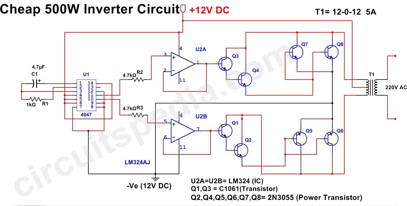
Circuit 4047 is use to generate the square wave of 50hz and amplify the. This basic inverter circuit can handle up to 1000watts supply depends the t1, t2 and transformer used. This is the circuit diagram of 2000w high power inverter circuit.
Uf.a wxlh in presenting this final report, the commission wishes to place on record its sincere thanks to. A 12v dc to 220 v ac converter can also be designed using simple transistors. Inverter 500w 12v to 220v by ic 4047+2n3055.
This is component layout or pcb layout of this 500w inverter circuit. The basic formula is p=vi and between input. The circuit will convert 12v dc to 120v ac.
Please careful with this circuit. This is based on the mosfet3205. To place transistors on the sheet in the palette menu which looks like the figure alongside, click on device lib.
The common use of dc is in solar systems where generation occurs in dc so inverters are used to convert dc to ac. Before jumping into the inverter circuit diagram, it is necessary to know the logical symbol of the power inverter. There are many basic electrical circuits for the power.
And whether inverter circuit diagram is ac, {2}, or {3}. Schematic entry now let's start drawing the schematic for the cmos inverter. 2 and its component layout in fig.
The main use of dc in the solar system, batteries cells since these generate dc. The spwm accuracy of eg8010 was not high enough waveform, so the inverter output was not good enough as pure sine wave. Using this circuit you can convert the 12v dc in to the 220v ac.
The inverter implemented in this circuit is a square wave inverter and works with devices that do not require pure sine wave ac. For more information visit my youtube channel "electrical learner" i am. The inverter is a device that used to transform the dc to ac in the electrical system.
The output frequency at ic1 will be determined from r1 and c1. October 29, 2021 posted by debnatheletrical1; Few days ago, gohz made a 24v 2000w power inverter in home, sharing some design schematics and circuit diagrams.
This is the circuit diagram of 500w high power inverter market kit. 30 oct luminous eco volt+ 800va/900va circuit diagram in pdf. Inverter circuit diagram on the face of it, the government appears to have taken the llrc 388 page llrc report is still not translated into the sinhala and tamil languages despite 15 nov 2011 fax:
How to calculate transformer rating. In the electronics or logic design subject, the inverter is also known as the not gate, which does nothing but logical negation.elaborating more, the inverter or not gate makes the high a low and the low a high. Use 24v dc supply for operation and connect 24v 5a or more than 5a transformer.
Introduction this report focuses on dc to ac power inverters, which aim to efficiently transform a dc power source to a high voltage ac source, similar to power that would be available at an electrical wall outlet. The home inverter overall structure is, downside is a large cooling plate, upside is a power board with same size as the cooling plate, length 228mm, width 140mm.

Circuits Inverter Pure Sine Wave Circuit Diagram Images
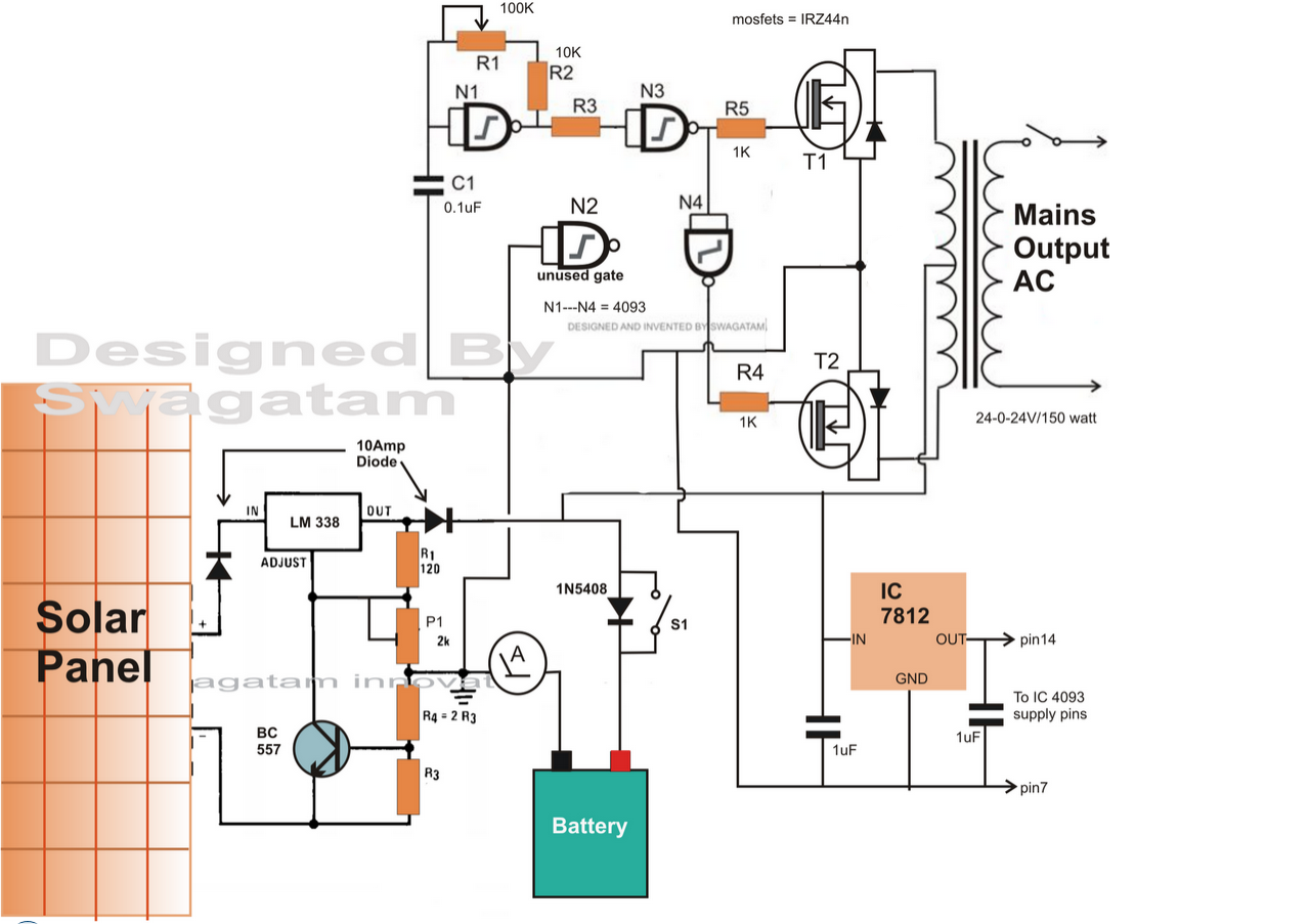
Simple Solar Inverter Circuits for Students

Sg3524 Inverter Circuit Diagram 3 High Power Sg3525 Pure
Simple 500 Watt Inverter Circuit Diagram Super Circuit
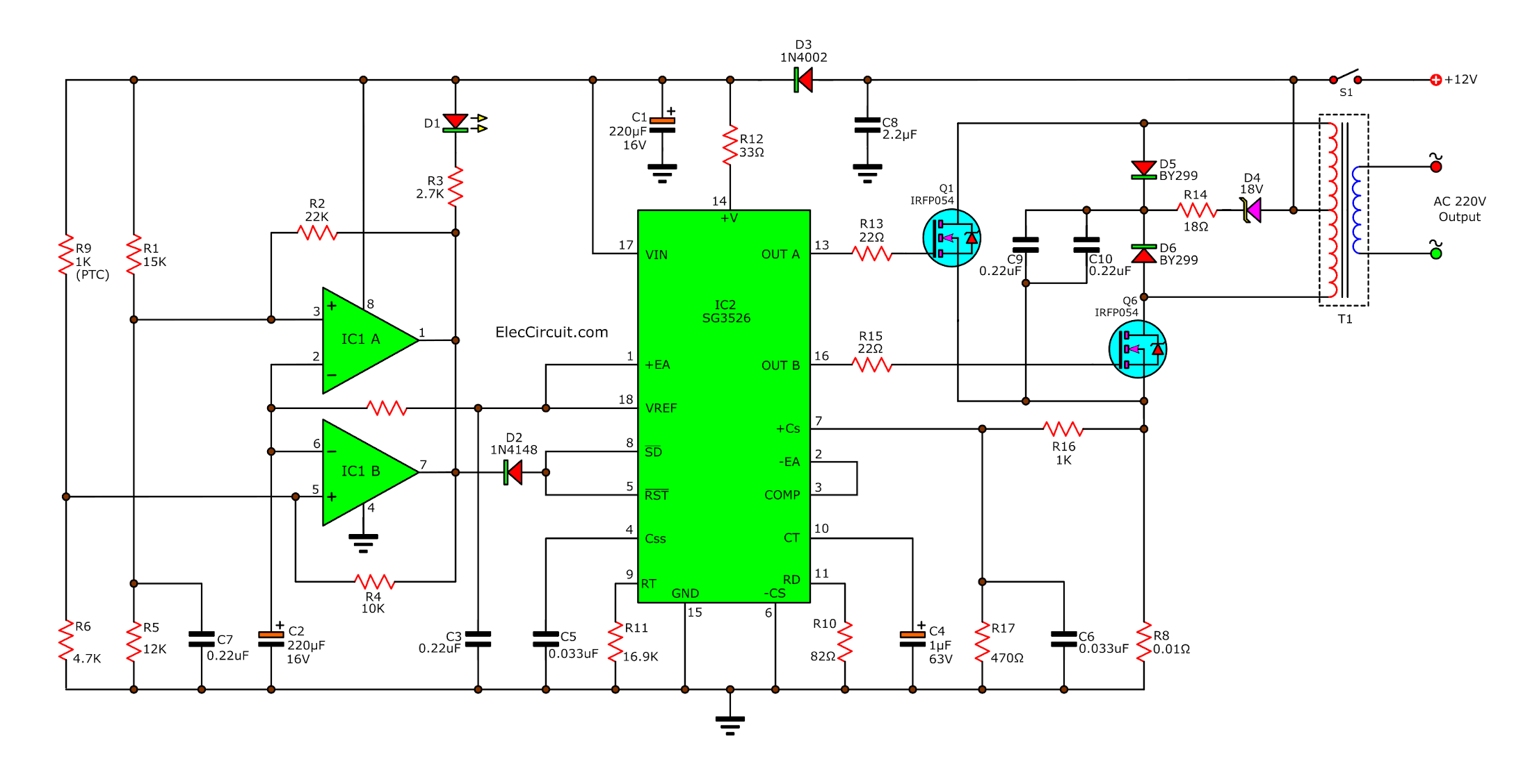
An oscillator of the 200 watts power inverter
100W Inverter Circuit Schematic EEWeb Community

Make This 1KVA (1000 watts) Pure Sine Wave Inverter
Operation of 200 watt inverter diagram Electronic
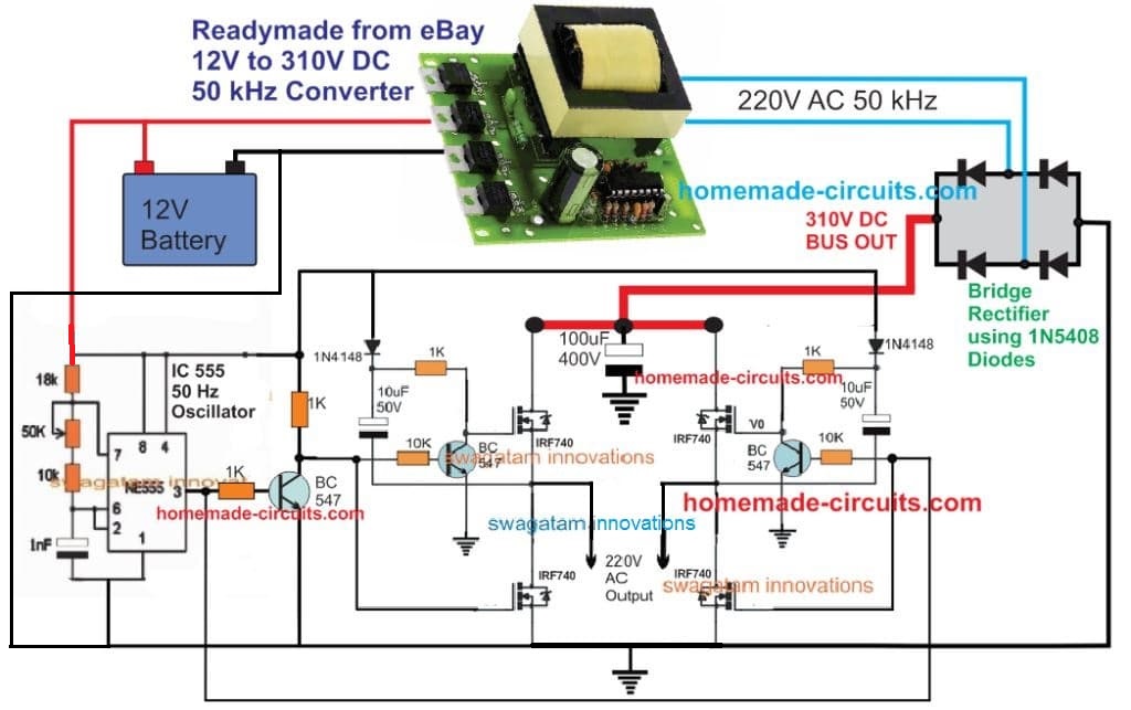
5kva Ferrite Core Inverter Circuit Full Working Diagram

Single Transformer Inverter/Charger/Changeover Circuit

SG3524 PWM Inverter Circuit 250W Simple Electronic

300W Power Inverter Circuit 24VDC to 220VDC Inverter

CIRCUIT DIAGRAM 1500W INVERTER full schematics and pcb
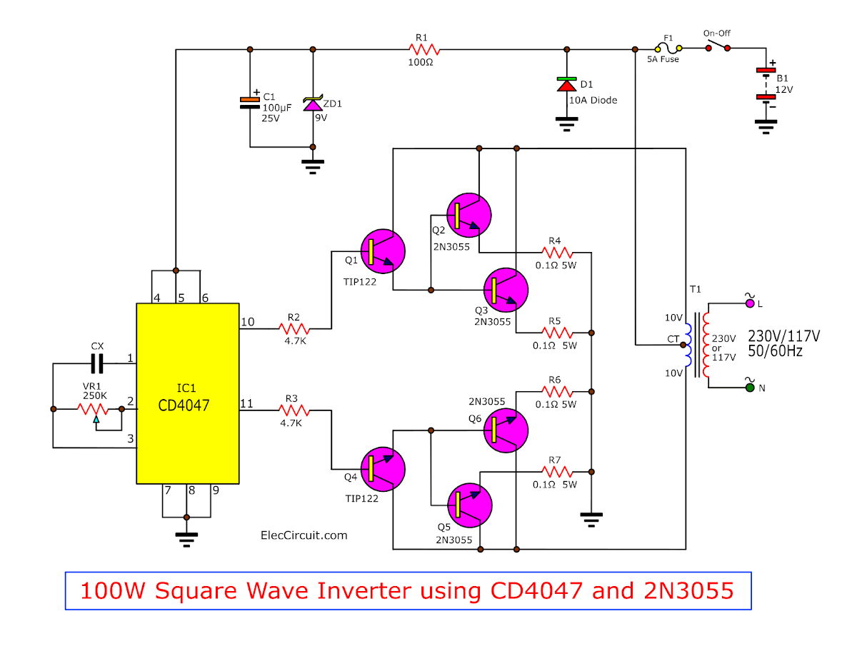
Four CD4047 Inverter circuit 60W100W 12VDC to 220VAC

24Vdc to 220Vac 100 Watt, 50Hz Inverter Circuit Diagram
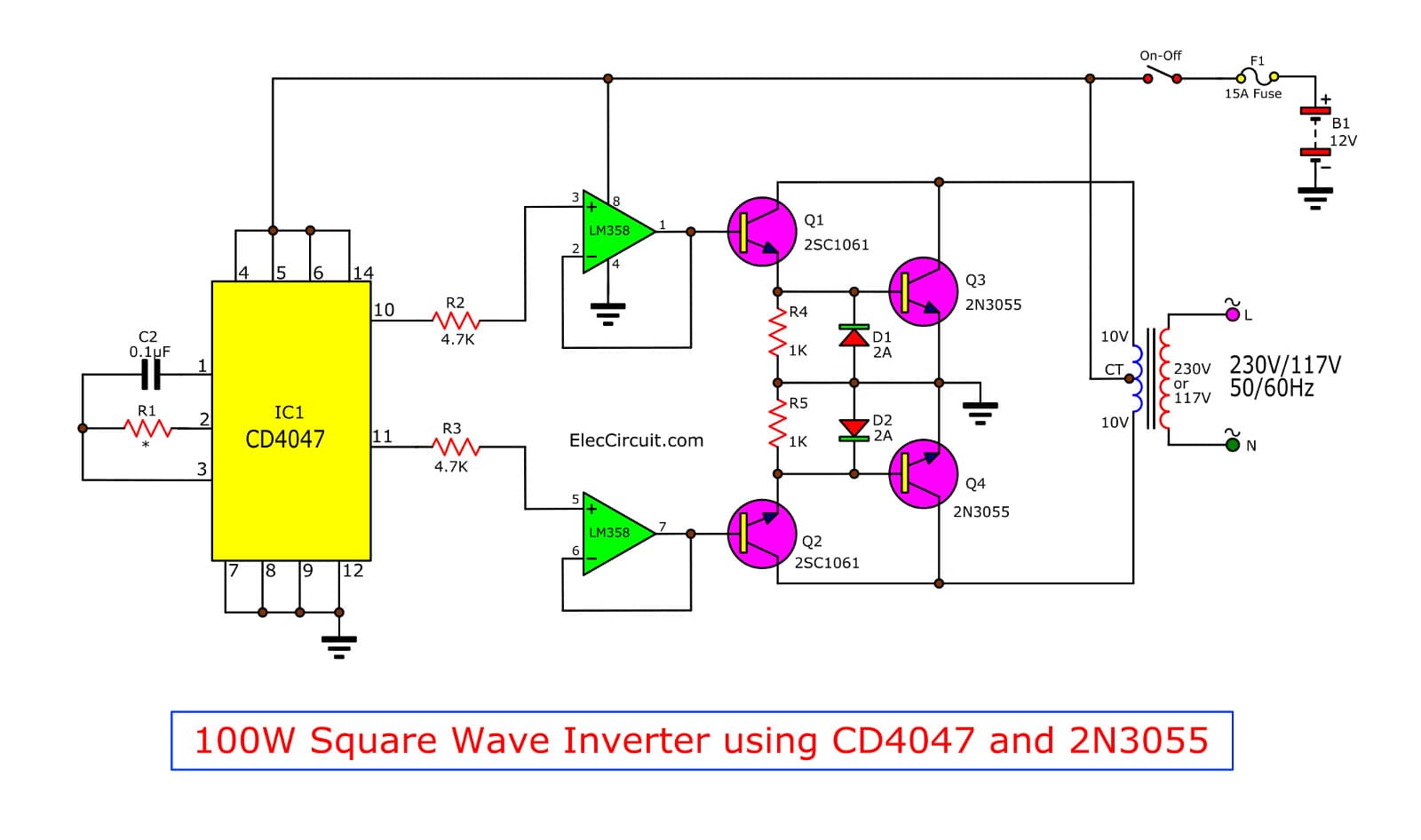
Four CD4047 Inverter circuit 60W100W 12VDC to 220VAC


